6 Wire Stepper Motor Wiring Diagram
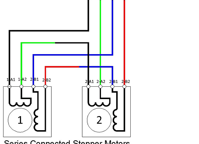
Red and blue are the first coil, green and black are the second, and if you wire them to the driver in that order, it will just work. Print the wiring diagram off plus use highlighters to trace the signal.
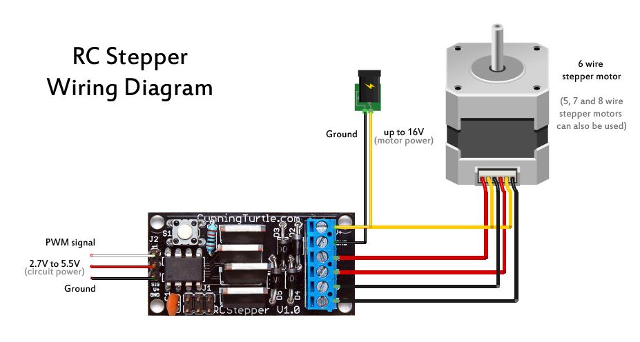
Radio Controlled Stepper CunningWiki
Nema 23 stepper motor datasheet specs applications.

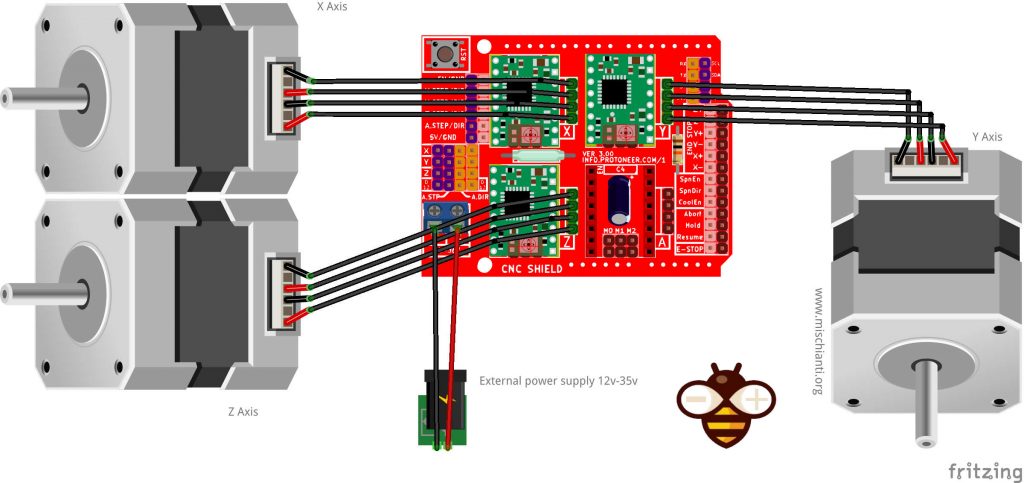
6 wire stepper motor wiring diagram. Stepper motors with these center taps are often referred to as unipolar motors. This motor can only be driven as a unipolar motor. The basic wiring diagram is shown below in figure 2.
Effectively read a electrical wiring diagram, one offers to know how the particular components in the program operate. Moons stepper motor wiring diagram. 1 trick that we 2 to printing a similar wiring plan off twice.
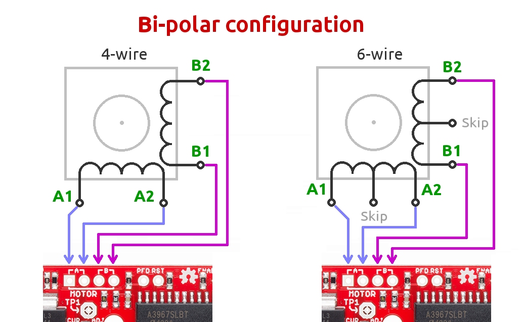
Bipolar stepper motors have two windings, which are not connected to each other, wired internally like this: Stepper motors with six wires are unipolar and have one winding per phase like the bipolar steppers but with a center tap. Arduino 6 wire stepper motor tutorial :
These days, most of the time, it's red, blue, green, black, in that order. How to use an old six wire stepper motor and control it with an arduino. 6 wire stepper motor wiring diagram.
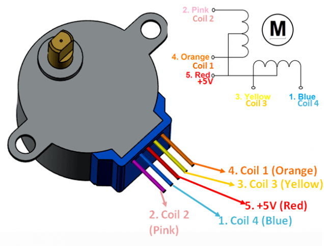
Bipolar stepper motor wiring diagram wiring diagram is a simplified gratifying pictorial representation of an electrical circuit it shows the components of the circuit as simplified shapes and the talent and signal associates amid the devices. All of the common coil wires are tied together internally and brought out as a 5th wire. This was an old stepper motor that i pulled out my junk.
It stands for the physical parts of the electrical circuit as geometrical shapes, with the real power and also link connections between them as slim sides. The installation of the ignition and starter switch requires the use of another three position 6 pole terminal switch. If not, the structure won’t function as it should be.
For instance , if a module is usually powered up also it sends out a signal of fifty percent the voltage plus the technician would not know this, he would think he offers a challenge, as he. But today i can say that this type of engine. Note, however, that if you are using the pololu standard connections, they have the phases ordered:
Longs stepper motor wiring diagram. Each phase nema 17 dimensions wiring diagram. March 10, 2020 by masuzi.
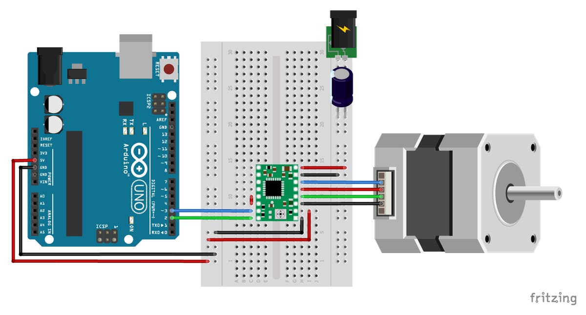
Arduino stepper motor tutorialhow to use an old six wire stepper motor and control it with an arduino. A stepper motor controller with driver circuit. 6 wire and 8 stepper motors nema 23 stepper motor datasheet specs 6 wire and 8 stepper motors moons free cad models nema ms17hd.
Suggested electric fan wiring diagrams page 1 these diagrams show the use of. The basic wiring diagram is shown below in figure 2. Arduino 6 wire stepper motor tutorial:
6 wire stepper motor wiring diagram from i.stack.imgur.com. The circuit diagram for the arduino stepper motor control project is shown above. If your stepper motor has 4 wires, it is a bipolar stepper motor.
Each component should be set and connected with different parts in particular manner. Difference between 4 wire 6 and 8 stepper motors national instruments. Arduino stepper motor tutorialhow to use an old six wire stepper motor and control it with an arduino.
This wiring configuration is best suited for applications requiring high torque at relatively low speeds. There are slight differences on how the different variant of stepper motors work ie. Servo wire colors chinese and american rc groups color coding color technology.
Account suspended stepper motor printer 3d printer. It stands for the physical parts of the electrical circuit as geometrical shapes, with the real power and also link connections between them as slim sides. If not, the structure won’t function as it should be.
This was an old stepper motor that i pulled out my junk pile, i'm not sure what it came from, i think it was an old printer from the 80s. When you make use of your finger or perhaps the actual circuit with your eyes, it is easy to mistrace the circuit. Since coils a and b on the diagram above are not connected, the resistance between leads a1 and b1, or between a1 and b2 will be infinite.
6 wire stepper motor wiring diagram. Schematic diagram stepper motor wiring schematic and wiring diagram electrical circuit diagram wire inverter welding machine. The 4 wires 5 wires and 6 wires stepper motors.
Due to the low resistance windings used in stepper motors, care must be taken to make sure that the current delivered to the board does not exceed 2a. It is not realistic to sort out all of the possible combinations of connections with an ohmmeter or by feel.
Stepper motor wiring Troubleshooting V1 Engineering Forum
6 Wire Stepper Motor Wiring Diagram Collection Wiring Collection

DRV8880 2A Stepper Motor Driver With AutoTune
Difference Between 4Wire, 6Wire and 8Wire Stepper Motors National Instruments

Stepper Motor Wiring Diagram — UNTPIKAPPS
I can’t begin to knowing… OnTableTop Home of Beasts of War
Stepper Motor Wiring Diagram Wiring Diagram Schemas

Transistor Bipolar Unipolar

Stepper Motor Wiring Diagram Wiring Diagram Schemas

6 Wire Stepper Motor Wiring Diagram Collection Wiring Diagram Sample
6 Wire Stepper Motor Wiring Diagram Collection Wiring Diagram Sample
Connecting A 6 Lead Motor to the Stepper Driver Basic_Circuit Circuit Diagram
42 6 Wire Stepper Motor Wiring Diagram Wiring Diagram Source Online


6 Wire Stepper motor with only 1 Center tap Electrical Engineering Stack Exchange
![]()
6 Wire Stepper Motor Wiring Diagram Collection Wiring Diagram Sample
How to drive a stepper motor simplified beginner's guide with common questions DIY Projects

รู้จัก Stepping Motor
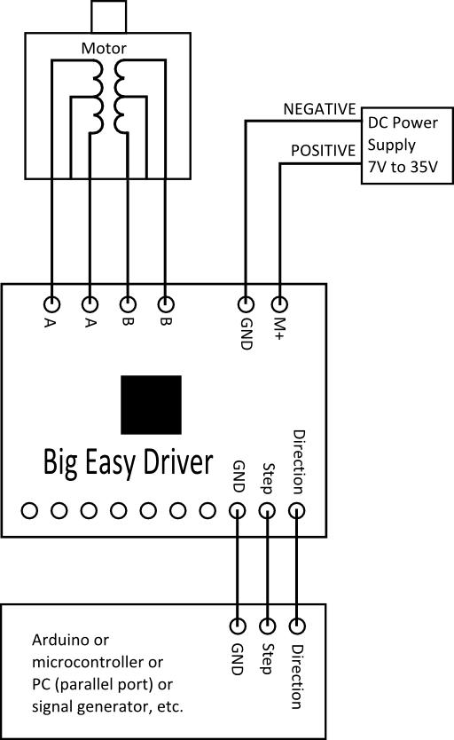
Big Easy Driver stepper motor driver
Stepper Motor Wiring Diagram 6 Pin Plug Complete Wiring Schemas