Pool Timer Wiring Diagram
Rewire the pool timer noting where line, load and neutral terminals are. It seems more of a.

Intermatic 240v Timer Wiring Diagram Free Wiring Diagram
Find your intermatic pool timer wiring diagram here for intermatic pool timer wiring diagram and you can print out.
Pool timer wiring diagram. March 31, 2019 by larry a. May 23, 2021 on intermatic pool timer wiring diagram. Attach the white 115 v wire to terminal 1 of line 1 l1.
A wiring diagram is a type of schematic which utilizes abstract pictorial signs to reveal all the interconnections of components in a system. It consists of instructions and diagrams for different types of wiring techniques and other products like lights, windows, and so forth. A wiring diagram is a type of schematic which uses abstract pictorial symbols to demonstrate each of the interconnections of components in the system.
Injunction of two wires is generally indicated by black dot to the intersection of 2 lines. Sometimes the wires will cross. Ge pool timer wiring diagram wiring diagram is a simplified welcome pictorial representation of an electrical circuit.
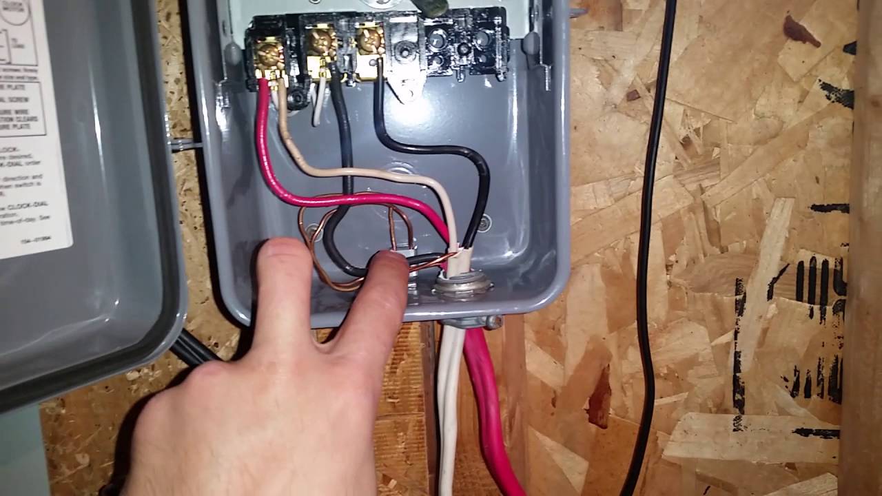
Schematron.org in this video i show you how to connect the wires in a volt pool pump. October 5, 2019 1 0. Check out the diagram below, or see the wiring diagram which comes with a new timer, or is printed on the door of the timer box.
But, it doesn’t mean link between the wires. According to earlier, the traces in a intermatic pool timer wiring diagram represents wires. Correct preparation will save hours of time and maybe even a 'stuck wire'.
But it doesnt mean link between the wires. A wiring diagram is a type of schematic which utilizes abstract pictorial signs to reveal all the interconnections. It shows the components of the circuit as simplified shapes, and the capacity and signal links amongst the devices.
It shows the components of the circuit as streamlined forms, as well as the power and signal connections in between the devices. A wiring diagram is a type of schematic which utilizes abstract pictorial signs to reveal all the interconnections of components in a system. Tighten down screws in each terminal so wire is secure.
Pool pump timer wiring diagram computer wiring diagram pool wiring diagram basic. Connect the ground wire to the green screw. Jan 13, · inground pool wiring diagram hey guys, does anyone have a wiring diagram for an inground pool that show the equipotential bonding grid.
A pool pump timer interrupts the electric circuit powering the pump motor during off use periods. Variety of swimming pool timer wiring diagram. Pool pump timer bypass in 240v system intermatic wiring t104 off with heater delay circuit suraielec 7 day basic repair grasslin t104r won t turn on problem what else to do solarattic solar.
After securing the wire conduit (flexible or rigid) to the box knock out with the proper 3/4″ conduit connector, first secure the green ground wire to the green ground screw, shown as gr. A wiring diagram is a streamlined traditional pictorial representation of an electrical circuit. Wiringall.com wiringall.com 1) diagram 1 showing how to change wiring:
It shows the components of the circuit as simplified shapes and the faculty and signal connections amongst the devices. The precision timer should be rewired with the same terminal numbers as the original timer. There will be primary lines that are represented by l1, l2, l3, and so on.
Intermatic pool timer wiring diagram just whats wiring diagram. You’ll be able to always depend on wiring diagram being an essential reference that may assist you to preserve money and time. An intermatic timer switch saves electricity when it turns a water heater off at night and when it limits the amount of time a pool s filtration system runs.
Compare the old electrical wiring diagram on the cover door with the precision wiring diagram provided. Sometimes, the wires will cross. A wiring diagram is a simplified standard photographic depiction of an electric circuit.
It’s easy to obtain puzzled about electrical wiring diagrams and also schematics. It includes instructions and diagrams for various varieties of wiring methods as well as other items like lights, windows, and so on.
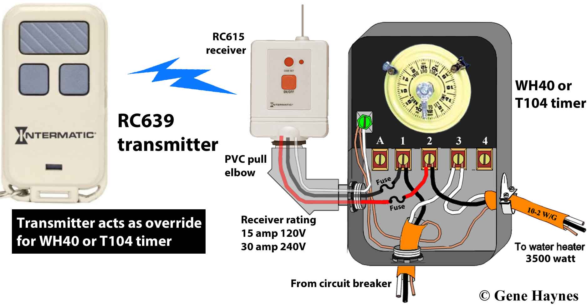
Intermatic Pool Timer Wiring Diagram Load Management
![]()
Intermatic Pool Timer Wiring Diagram Free Wiring Diagram

Intermatic Pool Timer Wiring Diagram Free Wiring Diagram
Intermatic Pool Timer Wiring Diagram Diagram Intermatic E10694 Pool Timer Wiring Diagram Full
Inground Pool pump / Timer wiring Community Forums


Inground Pool pump / Timer wiring Community Forums

I have replaced my pool pump timer with a new intermatic timer (T104M) I wrote down the wire

Intermatic R8806p101c Wiring Diagram Collection
Grasslin Pool Timer Wiring Diagram Wiring Diagram

Intermatic Photocell Wiring Diagram Download

How To Wire A Light Switch Timer Perfect Fresh Intermatic Pool Timer Wiring Diagram Irelandnews

Intermatic 240v Timer Wiring Diagram

Intermatic Pool Timer Wiring Diagram Free Wiring Diagram

Intermatic Timer T104 Wiring Diagram Download
Intermatic T101 Timer Wiring Diagram Free Diagram For Student

Swimming Pool Timer Wiring Diagram Hanenhuusholli

Intermatic Pool Pump Timer Wiring Diagram
![]()
Intermatic Pool Timer Wiring Diagram Free Wiring Diagram
33 Intermatic Pool Timer Wiring Diagram Wiring Diagram Database
